Fitting Torque Specifications — Learn Fittings
SAE J514 recommended min/max torque tables for JIC 37°, ORFS face seal, SAE O-ring boss, BSP, and DIN metric fittings, plus crowfoot torque adjustment.
To ensure leak-proof connections, hydraulic couplings must be tightened with precision. Applying torque values that exceed the maximum recommendation of your coupling manufacturer can distort or crack the fitting; under-tightened, a connection may fail to seal. The tables below provide minimum and maximum recommended torques regulated by SAE J514 standards — these are for qualification testing only, so set up your production environment based on the specific recommendations from your supplier.
Lubricate O-rings before installing
Lubricate all O-rings prior to installing in flange heads and grooves. This reduces the risk of damaging the seal during insertion and can reduce the maximum recommended torque by up to 25%.
Torque adjustments (crowfoot)
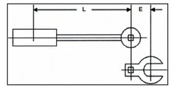
When using a crowfoot wrench with a torque wrench, factor in the distance E between the center of the drive socket and the center of the crowfoot. Add E to your setting to keep the reading accurate and avoid over-tightening.
Actual Torque = ((E + L) ÷ L) × (torque wrench reading)
- L — length of the torque wrench, in inches, feet or meters
- E — crowfoot offset, in inches, feet or meters
- Torque in lb-in, lb-ft or Newton-meters
Example: torque wrench reading = 45 lb-ft, E = 1.5″, L = 12″ → Actual Torque = ((1.5 + 12) ÷ 12) × 45 = 50.6 lb-ft (about 10% higher than indicated).
JIC 37° & 45° (machined or flared)
| Dash | Inches | Steel min (ft-lb) | Steel max (ft-lb) | Steel min (N·m) | Steel max (N·m) | Brass min (ft-lb) | Brass max (ft-lb) | Brass min (N·m) | Brass max (N·m) |
|---|---|---|---|---|---|---|---|---|---|
| -4 | 1/4 | 10 | 11 | 13 | 15 | 5 | 6 | 6-3/4 | 9 |
| -5 | 5/16 | 13 | 15 | 18 | 20 | 7 | 9 | 10 | 13 |
| -6 | 3/8 | 17 | 19 | 23 | 26 | 12 | 15 | 17 | 20 |
| -8 | 1/2 | 34 | 38 | 47 | 52 | 20 | 24 | 27-2/3 | 33 |
| -10 | 5/8 | 50 | 56 | 69 | 76 | 34 | 40 | 46-1/3 | 55 |
| -12 | 3/4 | 70 | 78 | 96 | 106 | 53 | 60 | 72-1/3 | 82 |
| -16 | 1 | 94 | 104 | 127 | 141 | 74 | 82 | 100-1/2 | 111 |
| -20 | 1-1/4 | 124 | 138 | 169 | 188 | 75 | 83 | 101-1/2 | 113 |
| -24 | 1-1/2 | 156 | 173 | 212 | 235 | 79 | 87 | 107 | 118 |
| -32 | 2 | 219 | 243 | 296 | 329 | 158 | 175 | 214 | 237 |
Flat-face O-ring seal — ORFS (steel)
| Dash | Inches | N·m min | N·m max |
|---|---|---|---|
| -4 | 1/4 | 14 | 16 |
| -6 | 3/8 | 24 | 27 |
| -8 | 1/2 | 43 | 54 |
| -10 | 5/8 | 60 | 75 |
| -12 | 3/4 | 90 | 110 |
| -14 | 7/8 | 90 | 110 |
| -16 | 1 | 125 | 240 |
| -20 | 1-1/4 | 170 | 190 |
| -24 | 1-1/2 | 200 | 245 |
SAE O-ring boss — ORB (steel)
| Dash | Inches | ft-lb min (≤4,000 psi) | ft-lb max (≤4,000 psi) | N·m min (≤4,000 psi) | N·m max (≤4,000 psi) | ft-lb min (>4,000 psi) | ft-lb max (>4,000 psi) | N·m min (>4,000 psi) | N·m max (>4,000 psi) |
|---|---|---|---|---|---|---|---|---|---|
| -3 | 3/16 | – | – | – | – | 8 | 10 | 11 | 13 |
| -4 | 1/4 | 14 | 16 | 20 | 22 | 14 | 16 | 20 | 22 |
| -5 | 5/16 | – | – | – | – | 18 | 20 | 24 | 27 |
| -6 | 3/8 | 24 | 26 | 33 | 35 | 24 | 26 | 33 | 35 |
| -8 | 1/2 | 37 | 44 | 50 | 60 | 50 | 60 | 68 | 78 |
| -10 | 5/8 | 50 | 60 | 68 | 81 | 72 | 80 | 98 | 110 |
| -12 | 3/4 | 75 | 83 | 101-1/2 | 113 | 125 | 135 | 170 | 183 |
| -14 | 7/8 | – | – | – | – | 160 | 180 | 215 | 245 |
| -16 | 1 | 111 | 125 | 150 | 170 | 200 | 220 | 270 | 300 |
| -20 | 1-1/4 | 133 | 152 | 180 | 206 | 210 | 280 | 285 | 380 |
| -24 | 1-1/2 | 156 | 184 | 212 | 250 | 270 | 360 | 370 | 490 |
BSP 30° inverted cone — British
| Dash | Inches | ft-lb min | ft-lb max | N·m min | N·m max |
|---|---|---|---|---|---|
| -2 | 1/8 | 7 | 9 | 9 | 12 |
| -4 | 1/4 | 11 | 18 | 15 | 24 |
| -6 | 3/8 | 19 | 28 | 26 | 38 |
| -8 | 1/2 | 30 | 36 | 41 | 49 |
| -10 | 5/8 | 37 | 44 | 50 | 60 |
| -12 | 3/4 | 50 | 60 | 68 | 81 |
| -16 | 1 | 79 | 95 | 107 | 129 |
| -20 | 1-1/4 | 127 | 152 | 172 | 206 |
| -24 | 1-1/2 | 167 | 190 | 226 | 258 |
| -32 | 2 | 262 | 314 | 355 | 426 |
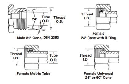
DIN metric — 24° / 30° cone (light & heavy series)
| Size | ft-lb min | ft-lb max | N·m min | N·m max |
|---|---|---|---|---|
| -6 | 7 | 15 | 10 | 20 |
| -8 | 15 | 26 | 20 | 35 |
| -10 | 18 | 30 | 25 | 40 |
| -12 | 22 | 33 | 30 | 45 |
| -14 | 26 | 37 | 35 | 50 |
| -15 | 30 | 52 | 40 | 70 |
| -18 | 44 | 74 | 60 | 100 |
| -22 | 59 | 89 | 80 | 120 |
| -28 | 74 | 111 | 100 | 150 |
| -35 | 133 | 184 | 180 | 250 |
| -42 | 148 | 221 | 200 | 300 |
Dry NPTF (tapered) pipe threads
NPTF tapered pipe threads are made up by turns past finger-tight rather than a single torque value. The published maximum recommended torque for dry NPTF starts at 20 ft-lb (25 N·m) for the smallest size; always follow your supplier's specification for the exact size and material.